2500 KVA Transformer Manufacturer IEEE CSA Standards
2500 kVA transformer has been exported by Daelim in recent years. In particular, Blockchain mining customers in North America have a particularly large demand, and even buy hundreds of units in bulk. Therefore, today I would like to introduce it to you.
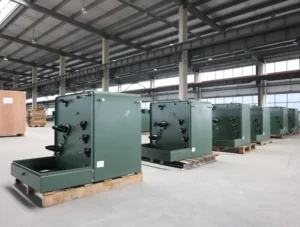
Pad-mounted Transformer
Dry-type Transformer
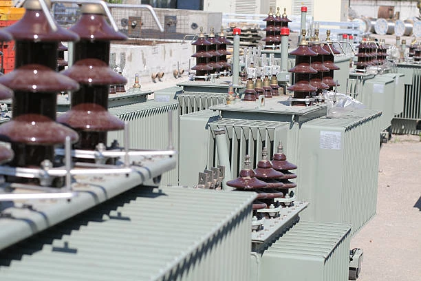
Oil immersed transformer
Table of Content
What is a 2500 kVA transformer?
A 2500kVA transformer is usually only the capacity of the transformer, the rated capacity you see on the transformer business card. 2500kva is also called apparent power (which includes active power and reactive power). Converting 2500kva into active power is about 2500*0.8=2000kw. That is to say, if your electrical equipment needs 2000kw of on-load power, You need to buy a 2500kva transformer.
Know more about The most complete explanation of grounding transformer
Types of 2500 kVA transformer
There are many types of 2500kVA transformers, such as single-phase and three-phase; oil-immersed transformers and dry-type transformers; box and substation transformers, as well as isolation transformers. The most used in Blockchain mining farms is 2500kva three phase pad mounted transformer and substation transformer, and the low voltage output is 415V.
Try for free High voltage transformer – 138kv power transformer
How much does a 2500 kva transformer weight
Because the design of each plant is different, the insulation grade of 2500KVA transformer is different, and the model and loss standard are different.
So there are all the differences. Below are 2500KVA pad mount transformer weight for you to reference, it is about 6000kg for one 2500KVA 24.94KV to 480V pad mount transformer.
Read my article on Know More About The Main Transformer – DAELIM
How much oil is in a 2500 kva transformer?
Also for reference, for 24.94KV to 480V 2500KVA pad mount transformer has about 1700L mineral oil in transformer.
In general, Pad mounted transformers are equipment mainly used for the distribution of energy. Our pad mounted transformers are connected to underground utility distribution lines, to reduce the primary voltage to the secondary voltage to be supply to the final customer, having different types depends on their configuration. This transformer can be single phase pad mounted transformer or three phase pad mounted transformer. Also we can difference in two type of configuration, such a radial feed or loop feed.
Read my article on Know More About The Main Transformer – DAELIM
How much does a 2500 kva transformer cost?
It depends on different factors, such as, the winding material you need copper or aluminum, transformer tank is normal tank or stainless steel tank and also the required efficiency value and losses, etc. According to the quantity and brand requirements of 2500kva transformer accessories, the price fluctuates greatly. Therefore, if you need to get the exact price of a 2500kva transformer, you need to provide the specific parameters and requirements of the transformer..Different specifications, different prices, the most normal 2500KVA pad mount transformer’s price is about USD 35K
Let’s know learn more about the NEW ZEALAND CUSTOMERS
How to calculate 2500 kva transformer losses?
– Experience in supplying multiple projects in American countries, such as USA and Canada
– Qualified with CSA certificate, SGS test report, UL certificate, etc.
– Complete after-sales service and installation teams in Canada, USA, etc
– Strong design ability for high efficiency, special ambient, low sound level, etc
– 6/7 weeks production time
Keep on reading 110 kv Oil Filled Power Transformer – DAELIM BELEFIC
WHAT ARE THE STANDARD SIZE OF 2000KVA TRANSFORMER?
Transformer loss is divided into iron loss and copper loss. Iron loss is also called no-load loss, which is its fixed loss, which is actually the loss generated by the iron core (also called iron core loss, and copper loss is also called load loss,
1. Transformer loss Calculation formula
(1) Active power loss: ΔP=P0+KTβ2PK——-(1)
(2) Reactive power loss: ΔQ=Q0+KTß2QK——-(2)
(3) Comprehensive power loss: ΔPZ=ΔP+KQΔQ—-(3)
Q0≈I0%SN, QK≈UK%SN
In the formula: Q0–no-load reactive power loss (kvar)
P0–no-load loss (kW)
PK–Rated load loss (kW)
SN–transformer rated capacity (kVA)
10%–Transformer no-load current percentage.
UK%–the percentage of short circuit voltage
B — average load factor
KT–load fluctuation loss coefficient
QK–Rated load leakage power (kvar)
KQ–reactive economic equivalent (kW/kvar)
The selection conditions of each parameter when calculating the above formula:
(1) Take KT=1.05:
(2) When the 6kV~10kV step-down transformer of urban power grid and industrial enterprise power grid takes the minimum load of the system, its reactive power equivalent
KQ=0.1kW/kvar;
(3) The average load factor of transformers, for agricultural transformers, B=20% is preferable; for dry industrial enterprises, the three-shift system is implemented, and B=75% is preferable
(4) Transformer operating hours T=8760h, maximum load loss hours: t=5500h;
(5) Transformer no-load loss PO, rated load loss PK, 10%, UJK%. see product information
2. Characteristics of transformer loss
P0–no-load loss, mainly iron loss, including hysteresis loss and eddy current loss:
Hysteresis loss is proportional to frequency: proportional to the power of the hysteresis coefficient of the maximum magnetic flux density.
Eddy current loss is proportional to the product of frequency, maximum magnetic flux density, and thickness of silicon steel sheet.
PC–load loss, mainly the loss on the resistance when the load current passes through the winding, generally called copper loss. Its size varies with the load current
The change is proportional to the square of the load current: (and expressed by the standard coil temperature conversion value).
Load losses are also affected by the temperature of the transformer, while leakage flux from the load current can cause eddy current losses in the windings and stray losses in the metal parts outside the windings.
The total loss of the transformer ΔP=P0+PC
Transformer loss ratio = PC/PO
The efficiency of the transformer = PZ/(PZ+ΔP), expressed as a percentage; where PZ is the output power of the secondary side of the transformer.
You may interested in Oil Type transformer – DAELIM BELEFIC
3.Calculation of power loss:
The power loss of the transformer consists of iron loss and copper loss. The iron loss is related to the running time, and the copper loss is related to the size of the load. Therefore, the power loss should be calculated separately.
4. Calculation of iron loss electricity:
Iron loss electricity of different models and capacities, the calculation formula is:
Iron loss (kWh) = no-load loss (kW) x power supply time (hours)
The no-load loss (iron loss) of the distribution transformer can be found from the attached table, and the power supply time is the actual operating time of the transformer, which is determined according to the following principles:
(1) For users with continuous power supply, the calculation is based on 720 hours per month.
(2) The power supply is interrupted or the power is limited due to the power grid, and the calculation is based on the actual number of hours of power supply from the substation to the user. It cannot be calculated on the grounds that it is difficult to calculate, and it is still calculated according to the operation of the whole month.
The time should be deducted when calculating the iron loss.
(3) Users who are equipped with a product clock on the low-voltage side of the transformer shall calculate the power supply time accumulated by the product clock.
Know more about One article to understanding more about earthing transformer
5. Calculation of copper loss power:
When the load rate is 40% and below, it will be calculated and charged according to 2% of the monthly power consumption (read by the electric energy meter), the calculation formula
Copper loss (kWh) = monthly electricity consumption (kWh) x 2%
Because the copper loss is related to the load current (electricity), when the monthly average load rate of the distribution transformer exceeds 40%, the copper loss should be charged at 3% of the monthly electricity consumption.
Monthly electricity consumption when the load factor is 40%. The calculation formula of the load rate is: load rate=copy electricity/
In the formula: S– rated capacity of distribution transformer (kVA): T– full month calendar time, take 720 hours:
COS¢–power factor, take 0.80.
The loss of power transformer can be divided into copper loss and iron loss. Copper loss is generally 0.5%. Iron loss is generally 57%. The loss of dry-type transformer is smaller than that of oil-invasion type. Total loss: 0.5+6=6.5
Calculation method: 1000KVAx65%=65KVA
65KVAX 24 hours x 365 days = 568400KWT (degrees)
The labels on the transformers have specific data.
6.Transformer no-load loss
No-load loss refers to the power absorbed by the transformer when the secondary side of the transformer is open, and the primary side add-on rate is equal to the sine wave voltage of the rated voltage.
Generally, only the rated frequency and rated voltage are paid attention to, and sometimes the tap voltage and voltage waveform, the accuracy of the measurement system, the test instrument and the test equipment are not paid attention to.
The calculated value, standard value, measured value and guaranteed value of loss are confused again.
If the voltage is applied on the primary side and there is a tap, if the transformer is a constant magnetic flux voltage regulator, the applied voltage should be the tap voltage of the corresponding tap position of the power supply.
In the case of variable magnetic flux voltage regulation, since the no-load loss is different for each tap position, the correct tap position must be selected according to the technical requirements,
and the specified rated voltage must be applied, because during the variable magnetic flux voltage regulation, the primary side Always apply a voltage to each tap position.
It is generally required that the waveform of the applied voltage must be an approximate sinusoidal waveform.
Therefore, one is to use a harmonic analyzer to measure the harmonic components contained in the voltage waveform, and the other is to use a simple method to measure the voltage with an average voltmeter,
but with a voltmeter whose scale is RMS, and compare it with the reading of the RMS voltmeter. , when the difference between the two is greater than 3%, it means that the voltage waveform is not a sine wave, and the measured no-load loss should be invalid according to the requirements of the new standard.
For the measurement system, it is necessary to select the appropriate test circuit, and select the appropriate test equipment and instruments.
Due to the development of magnetically conductive materials, the wattage loss per kilogram is greatly reduced.
Manufacturers choose high-quality high-magnetically conductive grain-oriented silicon steel sheets or even amorphous alloys as magnetically conductive materials.
There are no holes in the seam and the full slope, and the non-stacked iron yoke process is adopted in the process.
The manufacturers are developing low-consumption transformers, especially the no-load loss has been greatly reduced.
Therefore, new requirements are placed on the measurement system. The capacity remains unchanged and the no-load loss decreases, which means that the power factor of the transformer decreases at no-load.
The small power factor requires the manufacturer to change and reform the measurement system.
It is advisable to use the three-wattmeter method to measure, choose a 0.05-0.1 class transformer, and choose a wattmeter with a low power factor.
Only in this way can the measurement accuracy be guaranteed. When the power factor is 0.01, the phase difference of the transformer will cause a power error of 2.9% when the phase difference is 1 minute.
Therefore, in the actual measurement, the current ratio and voltage ratio of the current transformer and the voltage transformer should be correctly selected.
When the actual current is much smaller than the current connected to the current transformer, the larger the phase difference and current error of the current transformer will be, which will lead to a larger error in the measured results.
Therefore, the current drawn by the transformer should be close to the rated value of the current transformer. current.
The concept of the measured value should also be correctly understood, either the reading of the inter-meter (or the reading of the power converter) or the measured value should be converted to the rated conditions, and must have sufficient accuracy.
For the measured value of no-load loss, the main reason is that the voltage waveform of the power supply should be a sine wave, and the difference between the average reading and the RMS pressure reading is less than 3%.
7. Calculation of no-load loss, load loss, and positive reactance voltage of transformer No-load loss:
When the primary winding of the transformer is open-circuited and the primary winding is applied with a rated voltage of a sinusoidal waveform of rated frequency, the active power consumed is called no-load loss.
The algorithm is as follows:
No-load loss = no-load loss process coefficient x unit loss x core weight
Load loss: When the secondary winding of the transformer is short-circuited (steady-state), the active power consumed when the primary winding flows the rated current is called load loss.
The algorithm is as follows:
Load loss = resistance loss of the largest pair of windings + additional loss
Read on POWER SUBSTATION IN GUAYAQUIL
Customized 2500kVA transformer
Daelim is a professional transformer designer and manufacturer, with a professional technical team, which can design various types and standards of 2500kva transformers for you. Whether you are from the United States, Canada, Mexico, Australia or Ecuador, our strong technical team can fully meet any requirements for your transformers and give you a satisfactory transformer solution. The Daelim team has nearly 20 years of experience in overseas business of transformers, and has got UL, C/UL and CSA certification. Daelim got qualification on selected transformer supplier list in USA markets.If you have a transformer business, you can negotiate with the Daelim team.